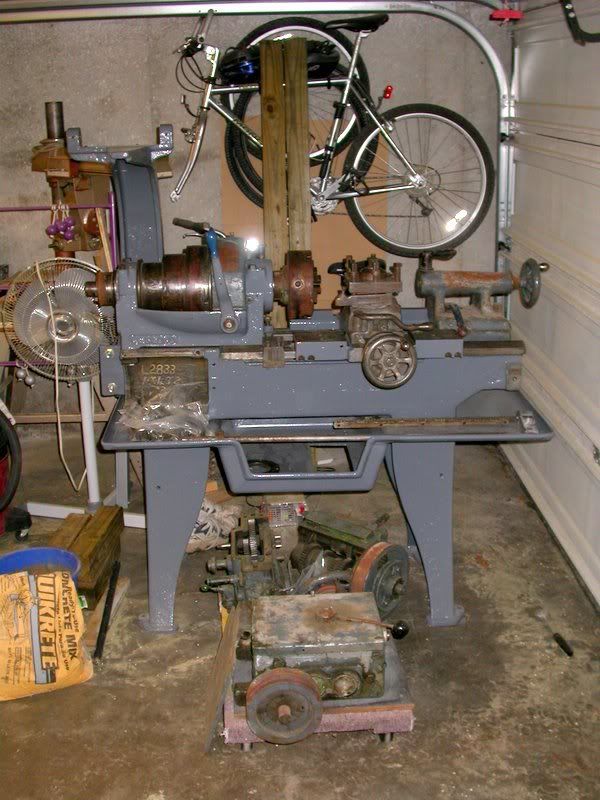
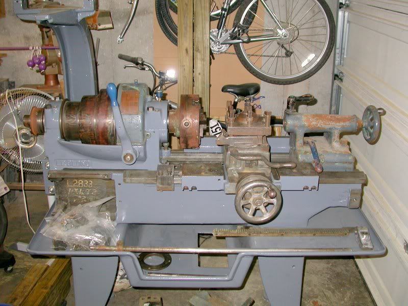
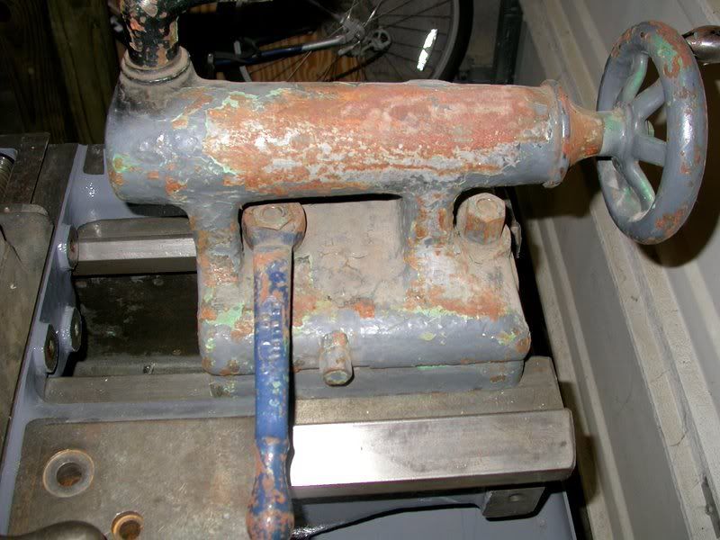
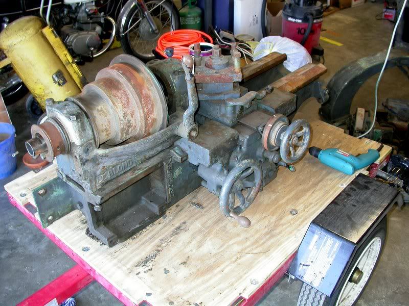
Friday, December 01, 2006

Time to move on

Wow, almost 3/4 of a year since my last post. Since then, I've gotten a little more done. But, the biggest change is that I purchased a 10" Sheldon lathe. This lathe will meet my needs much better than the Leblond, so it's time to find a new home for it. Here's some photos of how it is now.


This blog pretty well details what's been done. This is what still needs to be done:

*Paint cross slide and components
*Strip and paint tailstock
*Strip and paint headstock clutch cover
*Strip and paint apron
*Strip and paint feed gearbox
*Fix missing teeth on rack
*Strip and paint drive gearbox
*Design drive system (pulleys and flat belts need to be purchased)

The only parts missing from the lathe are some fasteners. Some are normal sizes, but some seem to be odd sizes (such as a 1/2-12 thread).

Here's a few more photos.


Tuesday, March 28, 2006

Spindle reassembled

I've now got the spindle reassembled. I don't have photos for a lot of it, so you'll just have to rely on the vivid imagery my words portray. ;)
The spindle needed to be taken completely apart to be cleaned, and to have the clutch lining replaced. The clutch allows you to engage and disengage the spindle from the cone pulley, so you don't need to stop the motor if you want to change something, and it also makes it easier to start up the motor, because you can start it without it having to start everything spinning right away. The clutch mechanism was a bit tricky to take apart, it was designed so that you could only put it together in a certain sequence, and there was just barely enough room to gets the parts in.

Here's a photo looking down onto the spindle before I took it apart.
Image hosting by Photobucket

Here's a shot of the right side of the spindle, with the clutch mechanism on the left side of the photo (ignore the red oval).
Image hosting by Photobucket

After taking it all apart, I found that the inside of the cone pulley looked like this:
Image hosting by Photobucket
From the feedback that I've gotten from the Practical Machinist Forum, the black spots are graphite.

A not so good photo of the clutch disc:
Image hosting by Photobucket
You can see the black clutch material, the metal disc that engages the cone pulley, and then another disc of clutch material behind it. The clutch material was originally rivetted to the metal disc. The clutch had worn down to where the rivets (they were copper) were worn through, and so the clutch material was no longer attached to the metal disc. The clutch was also very greasy, so I don't think it would have held very well. I ordered some new clutch material from McMaster-Carr:
Image hosting by Photobucket

I cleaned up the metal disc, then traced it onto the new clutch material. Using a RemGrit blade (no teeth, just tungsten carbide bonded to a smooth blade) in my jigsaw, I cut out new discs. I used epoxy, rather than rivets, to bond the new clutch material to the metal disc (sorry, no photos).

About this time I purchased a parts washer from Cummins Tools. Along with some parts washer solvent from Tractor Supply Co., I was able to easily clean the spindle parts (worked much better than the kitchen sink).

So, the spindle after cleaning and assembly:
Image hosting by Photobucket

The right side, compare this to the photo at the top of this post:
Image hosting by Photobucket

The left side:
Image hosting by Photobucket

And, a photo of the headstock, almost fully assembled:
Image hosting by Photobucket

I'll take care of the rust that's left on the pulleys after I get a motor hooked up. I can then sand off the rust using sandpaper while the motor spins the pulleys.

The next step is to attach the motor/gearbox mount to the back of the lathe:
Image hosting by Photobucket

This piece is pretty heavy, hopefully I can get my shop crane back into that corner.

Wednesday, February 01, 2006

Finished the carriage

I finished painting the carriage, and set it on the bed to see how it looks. I think it's neat:
Image hosting by Photobucket

I didn't paint all of the carriage, just the parts that weren't machined. I'll end up setting tools on the top of it, so I didn't paint those parts, since the paint would get chipped up. I've got a carriage stop that clamps onto the bed so that you can repeatedly turn to the same length, and that hits against the side of the carriage, so I didn't paint that, either. Also, there's 'OIL' words stamped in a few spots to indicate oiling points:
Image hosting by Photobucket

I thought it would be a shame to paint over those.

Next, I think I may work on the crosslide, it would be nice to have it looking more like a proper lathe with it on.
This is the crosslide:
Image hosting by Photobucket

And this is the indexable toolpost that goes on it:
Image hosting by Photobucket

I had been thinking about eventually rebuilding the crosslide to have t-slots, and then making a compound slide to go on that. But, now that I've got a horizontal milling machine, the t-slotted crosslide won't really be needed as much, so I may just go with building a compound slide for it.

Tuesday, January 31, 2006

More paint

Yep, still painting. Finished the headstock.
Image hosting by Photobucket

I took the spindle apart. I've got the cone pulley cleaned up. I found that the clutch disc inside needed replacing:
Image hosting by Photobucket

So, I ordered a sheet of clutch lining from McMaster:
Image hosting by Photobucket

Need to cut some rings out of that, then I can reassemble the spindle (maybe). I'm thinking of possible replacing the bearings, if I was ever going to do it, now would be the time. Here's a shot of the assembled spindle (before I took it apart):
Image hosting by Photobucket

Now I'm working on painting the carriage and the motor and gearbox mount:
Image hosting by Photobucket

I really need to find a motor to use for it. My current plan is to use a timing belt to run from the gearbox to the cone pulley, and if I use that, then I can't assemble the headstock until the belt is on. But, I can't buy the belt until I have the motor so that I know what length I'll need. A flat belt wouldn't require this, but a pulley for the gearbox that would work with a flat belt isn't cheap.

I've also thought about buying a 3 phase motor, and using a VFD with that. Then I wouldn't need the gearbox. I am purchasing a horizontal milling machine that also needs a motor, and I may be able to share the VFD with that.

Sunday, November 20, 2005

Painting

Well, since the last post there's been some progress. I took the legs, chip pan, and bed to the car wash and used the engine degreaser to clean them. That did a really good job; I didn't need to use anything else to clean them. I applied a coat of primer and a coat of paint to all these pieces, then assembled them. I used Magnet Paints, Battleship Gray for most of it, and will use Mack Blue for some accents. A photo of the lathe:


I'm now working on painting the parts of the headstock. I used some degreaser and a hose in the driveway to clean up the main casting, and scrubbed up the rest of the pieces in the sink. I've got one coat of primer and one coat of paint applied:


I've been considering options to power the lathe. The way it was previously setup, power was transmitted to a 6 speed gear box, then down to a v-belt pulley that was attached to the flat belt pulley on the powerfeed gearbox. A leather flat belt connected the pulley on the gearbox to the spindle. I'd rather transmit the power the way it's supposed to be, using the cone pulley on the spindle. With a 1750 RPM motor, if I have the pulley on the motor half the size of the one on the 6 speed gearbox, and then have the output pulley on the gearbox be half the size of the cone pulley, then I should get a decent set of speeds. I'm having a little trouble trying to find pulleys to fit the output of the gearbox. I may end up using a multi-v belt or synchronous belt and using a pulley to match that on the gearbox. The cone pulley on the spindle should have enough area touching the belt that it won't need grooves or notches in it.

Monday, June 20, 2005

No progress

Well, no new progress to report since the last post. I did try to clean a part of the chip pan using rubbing alcohol, but it took a lot of time to get one tiny section part way clean. I think I may try using a degreaser and a hose. I'm just worried that it's going to cause the parts to rust. Hopefully I can dry it off quickly enough that it won't. I think washing it with a degreaser, then cleaning it with rubbing alcohol may work well. There's just too much oil and grease left on it to really be able to clean it well with rags.

Monday, June 13, 2005

Almost ready to paint

No pictures with this post, but they wouldn't be exciting anyway. :)
I've pretty much finished scraping the paint off of the bed, the legs, and the chip pan. Now I just need to clean them up, and then I'll be ready to paint. I've seen suggestions that rubbing alcohol be used to clean the surfaces before painting. I hope to try that out soon.
I ordered paint a few weeks ago from Magnet Paints. I ordered a gallon of primer and a gallon each of Mack Blue and Battleship Grey. I plan on painting most of the machine with Battleship Grey, but then using the Mack Blue for detailed bits like controls and such. The price was pretty good, the total was about $63 for three gallons. Rustoleum at Home Depot costs around $30 a gallon, and I think the Magnet Paint is a better product. I should have plenty of paint left over, which I want to use on some of my other machines. I'm planning on rebuilding my drill/mill, and would also like to repaint it. Right now it's an awful orange color which is really thick, reminds me of Tempra paint.
My plan is to paint the legs, bed, and chip pan all together, then assemble the lathe with those pieces. It's the minimum that can be assembled, and it will give me a structure to place the other pieces onto as I work on the rest. That should make the project take up less space in the garage, too.

Saturday, May 14, 2005

Carriage rack removal

At some point in this lathe's life, the carriage was probably run into a stop or the headstock while the powerfeed was engaged. This caused a few of the teeth on the rack for the carriage to get sheared off.
Image hosted by Photobucket.com

I wanted to remove the rack so that I could clean it up better and also scrape the paint off the lathe bed in that spot, and also hopefully repair those two teeth. It's held on by three screws and two pins. The screws came out easily, but the pins didn't want to budge. I tried pounding on them from the inside of the bed with a punch and hammer, but I wasn't able to get very much of a swing on the hammer because of the width of the opening in the bed.

A pin from the outside:
Image hosted by Photobucket.com

A pin from the inside:
Image hosted by Photobucket.com

So, I posted my query to a forum, and got several ideas. I hoped that I would just be able to drive them out, because I really wanted to reuse them, and drilling them out would have ruined them. Fortunately, with application of some pentrating oil and some heat, along with lots of pounding, I was able to get them loose:
Image hosted by Photobucket.com

I haven't completely figured out how I'm going to fix the teeth. If I had a shaper (which I was actually planning on bidding on at the same auction I bought this lathe at, but figured after buying this that it was enough for one day) it would be pretty straightforward. I'll start by milling out a slot where the missing teeth are (I might even mill it out three teeth wide, and replace the tooth that is just to the right of the missing ones, since it's pretty rounded over). Then I'll braze or silver solder a block of steel in that slot. Then I'll need to cut the teeth. It's in the cutting of the teeth where the shaper would help. I need to think about it some more before I start on it.

Tuesday, April 26, 2005

Stripping the lathe

Currently, I'm in the middle of scraping and stripping the paint off of the lathe. There appears to be 3 or 4 coats of paint on it. The outer grey layer is flaking off in parts. Under that is a green layer. Below that is a blue layer. Below the blue layer there's some white filler, and then more grey paint. Because of the filler, I'm not sure if the original color was blue or grey. It seems strange that if it was repainted from grey to blue that they would add filler first.
I'm using various methods to strip the paint. For some of the smaller items, especially the ones that are steel and not cast iron, I'm setting them in a plastic tub of laquer thinner. After a good soak, I can usually easily scrape off a layer or two of paint. I did put one cast iron piece in the laquer thinner, but in addition to the paint, it stripped off the filler. So, now the casting is a little rough. You can kind of see it in the photo below:
Image hosted by Photobucket.com
I'm not sure if I'll put filler back on this piece, it's hidden under a cover, so no one will really see it.

The headstock has been stripped with a putty knife, a wire wheel in an angle grinder, and some paint stripper. I think the putty knife is the best way to go. The wire wheel left some scratch marks on the headstock. The paint stripper took off more filler than I really wanted to. So, I think I'm going to settle for just getting the loose paint off, giving it a sanding to smooth things out, and then painting it. It's mostly done, as seen in the picture below:
Image hosted by Photobucket.com

The lathe bed and legs are coming along pretty well. There's a lot of large flat spots, so it's easy to make quick progress. I'm going to scrape as much of the legs and bed as I can with them together, then I'll take them apart and finish the stripping. I'm undecided on how much I want to clean and paint on the inside of the bed. It's pretty griming and oily, and there's not a real good way to get in and scrape it all off. So, I'm tempted to leave it as it is, maybe just scrape off all the gunk that I can. But, if the rest of the lathe is all shiny, I'd hate to have that be an eye sore. However, it's going to get all grimy and oily again anyway, and I probably wouldn't wipe it down. So, that's still to be decided. Below is a photo of what it looks like now.
Image hosted by Photobucket.com

I've got the carriage stripped pretty well. It's ready for paint, but I need to decide how much of it I'm going to paint. Below is a picture of the carriage. This slides back and forth on the lathe bed.
Image hosted by Photobucket.com

On the carriage, there are spots that you need to oil occasionally. Some of these are marked with little arrows and an 'Oil' label stamped into the carriage. Below is a photo of one of these marks, with a penny shown for scale.
Image hosted by Photobucket.com

If I paint the top of the carriage, I don't think you'll be able to see the oil marks. I posted this question to a forum, and got varied answers. I think I'm probably going to paint it, since sanding it down to make it smooth and shiny would destroy the oil marks anyway. Click here to see the forum thread.

Below is a photo of the rest of the parts that I still have to strip. Quite a bit left to do, but I think it will look sharp when it's all done.
Image hosted by Photobucket.com

Friday, April 22, 2005

New lathe!

Buying the lathe
I picked up an 11" Leblond Rapid Production Lathe at an auction on April 1st, 2005. The auction was really quite a sight, there were tons of older machine tools. Most of them were pretty rusty. There was also a lot of line shafting there. I was there for the entire day on Friday, didn't bid on anything until the later part of the afternoon. Earlier in the day, there were quite a few things that I would have bid on, had I known that I was going to get this lathe. There were two Dumore Versa-mils, nifty lathe attachments that allow you to do milling and grinding on the lathe. I think they both sold for around $75 each. One was somewhat rusty, but the other was in decent shape. There were also some large lathe chucks, toolbits, etc, that I could have picked up cheap. But, at the time those were being auctioned, my only lathe was my 7x12 minilathe, and none of those items could be used on it. Anyway, right before this lathe came up for auction, I won choice on a pallet for $7.50, and picked up a can full of #1 and #2 morse drill collets. I had thought they were regular collets, which would have been nice on my 7x12, but I don't know if I'll ever use these. Might sell them on ebay. So, not too long after those sold, they got around to the LeBlond. They didn't have it out earlier in the day, so not too many people got a close look at it. They pulled it out after some other stuff in the area sold, and the crowd drifted along to what they were selling next. I wasn't particularly interested in that stuff, so I spent some time looking at the lathe. At first, I wasn't interested, because the piece that goes over the top of the rear bearing was missing. However, I looked further, and found that it was in a bucket with some bolts and such. Oh, I should mention that the lathe was taken apart. The carriage and headstock were on the lathe, but the spindle was sitting only halfway into the headstock. The legs were sitting next to it, as was the gear box for the power feed, and a gear box for the motor. So, at first glance it was difficult to tell if everything was there or not. I looked it all over, and found that everything important was there. I bid $50 to start, someone else bid $60, then I bid $70. No more bids, and it was mine. I was excited, but kept doubting as to whether I really got it for $70, or did I miss another number in front of that? Did I somehow end up buying it for $770? After the auction was over (I didn't buy anything else), I went up to pay, and sure enough, it was $70. I was happy to hear that!

Moving the lathe
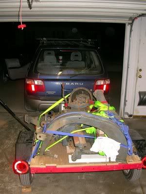
So, I was now the proud owner of a 1200 lb lathe. How was I going to load it? I had brought along my little trailer. It's a small trailer, but has been surprisingly useful. And since it is so small I can stand it up on end on the side of the garage, where it takes up little space. Anyway, there was a bobcat with forks available to help load if people needed help, which I thought I'd need to use. However, a kind soul at the auction thought that we could probably slide the bed off the cart it was on (an old railroad baggage cart) right onto my trailer, since they were about the same height. It was heavy, but it worked. With the lathe bed onto the trailer, I wasn't worried about the rest of it. Everything else I coud lift.
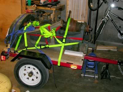
My first step to secure the lathe was to screw down some 2x4's that I'd brought along just for that purpose (thanks to my dad who raised me to always plan ahead and be prepared) to the plywood floor of the trailer. These blocks kept the lathe from moving around when accelerating, stopping, and turning. I didn't want the lathe bed sliding into the back of the Forester! Unfortunately, about halfway through screwing the blocks down, my cordless drill died. (At this point I thought it might be handy to convert ad old 12 volt cordless drill that has a dead battery into a corded 12 volt drill that could run off a cigarette lighter socket). I tried using a screwdriver, but there was just no way that I was going to be able to get the rest of the 3" screws in tight enough to hold the lathe in position. I made a few phone calls, and got ahold of my brother-in-law, whom I convinced to bring a cordless drill out to me. He zipped right out there with a friend, and I quickly had the screws in place. After seeing them off, I resumed my loading. With the lathe blocked in place, I started using a few ratchet straps to hold the lathe down. If the blocks could keep it from sliding around, and the straps could keep it from raising up, then it would be solid. A few straps over it, and it seemed to be good. I worked to load the rest of the lathe up onto the trailer. I fit the legs and a motor bracket onto the trailer, and put everything else into the back of the Forester. It was heavily loaded, but I didn't have far to go.
Image hosted by Photobucket.comImage hosted by Photobucket.com

Unloading the lathe

So, I had gotten the lathe home, but I now needed someway to unload it. All the pieces, except for the lathe bed, could be lifted off.
Image hosted by Photobucket.com
I gave some thought to just borrowing a shop crane from someone, but decided that it was probably best if I purchased one. I figured I'd be using it a lot as I was stripping off paint and getting it set up in my garage. I made a trip up to Harbor Freight to pick up a folding shop crane. I also purchased a load leveler while I was there, which was very handy to have. With this, I was able to lift the bed off the trailer.
Image hosted by Photobucket.com
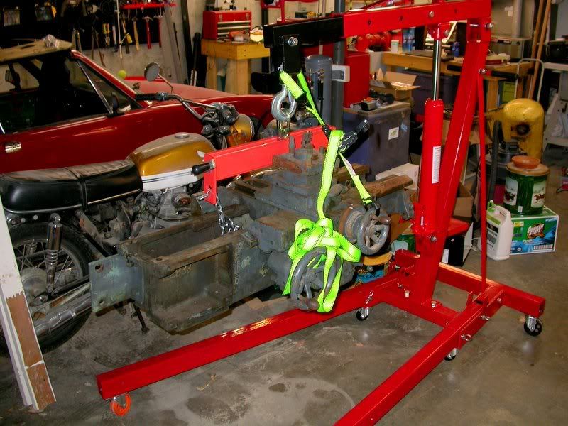
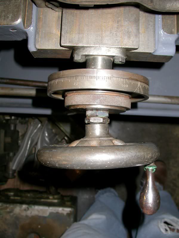
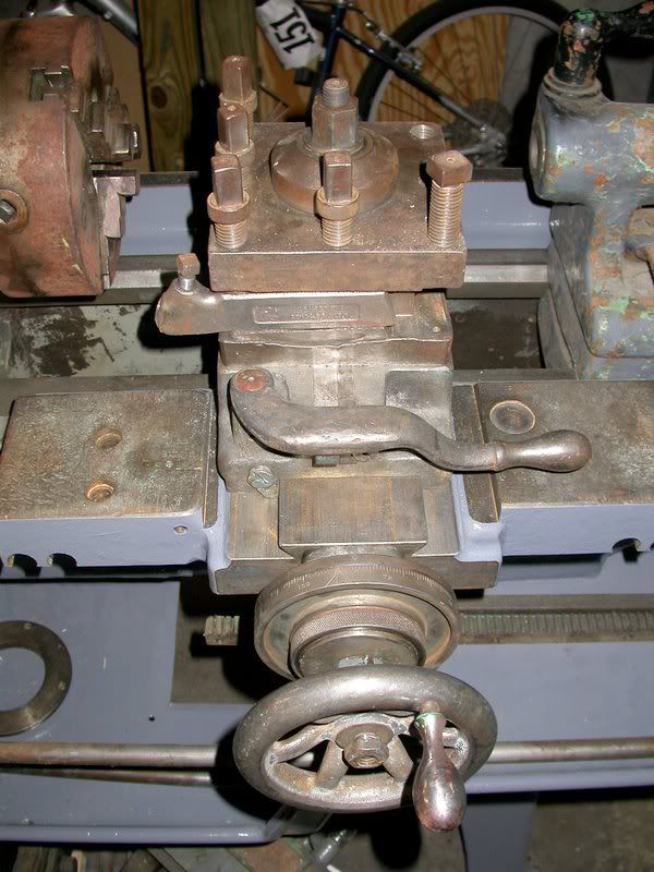
The load leveler and chain lifted most of the weight, but I need the ratchet strap on it to keep it from tipping over. The screw for the crosslide is bent, I think it was bent when I got the lathe, but I'm not sure. I hope I didn't bend it while using it as a lift point. I probably should have figured out a different way to secure it.
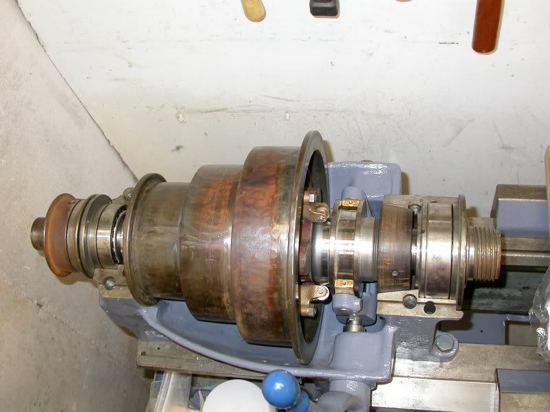
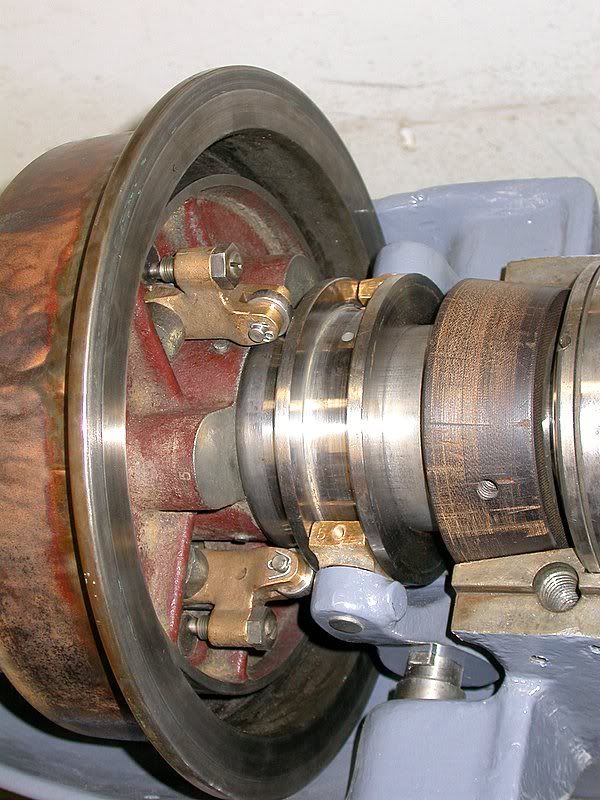
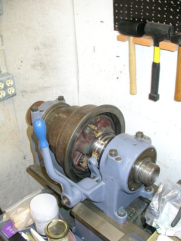
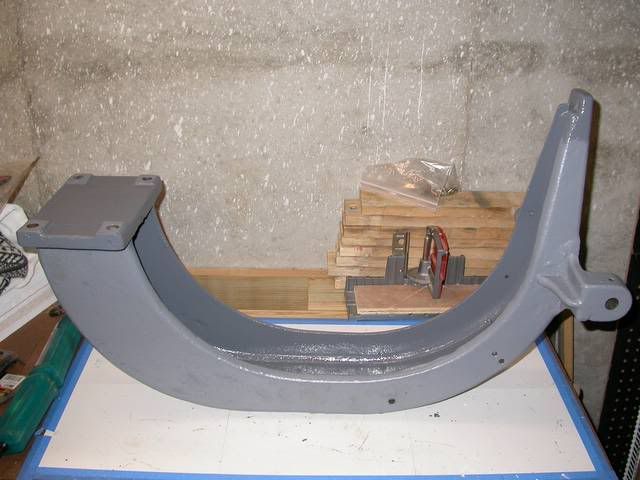
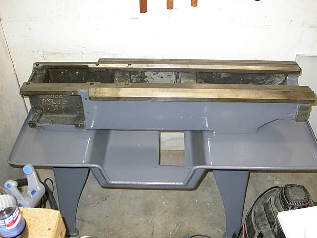
Setting up the lathe

With the lathe being held by the engine crane, I could attach the legs to the bed. The legs can stand by themselves, so I set one up under the bed, then lowered the bed until it was just above the leg. I bolted the leg to the bed using 3 of the 6 bolts I had gotten with the lathe that appear to be the right ones for this. I then set the other leg under the bed, and did the same. It was soon standing all on its own. I also used the shop crane to put the headstock onto the lathe. That was cool, I felt just like a big crane operator, slowly letting it down, aligning it with the bed.
Image hosted by Photobucket.com

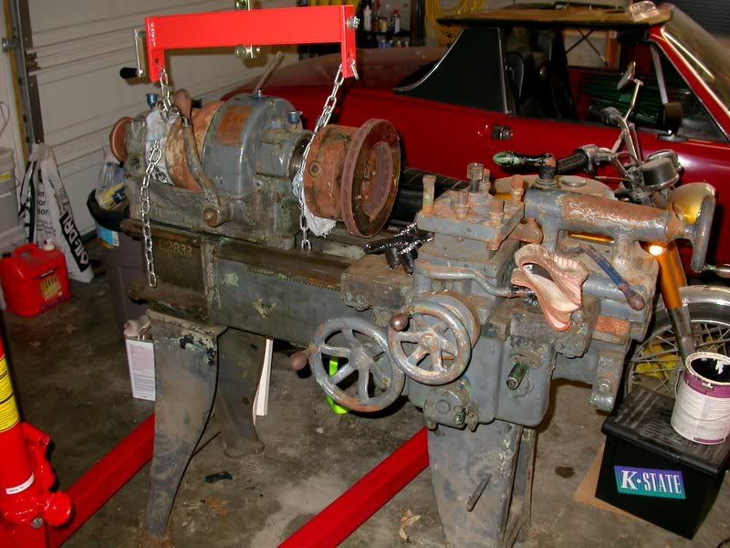
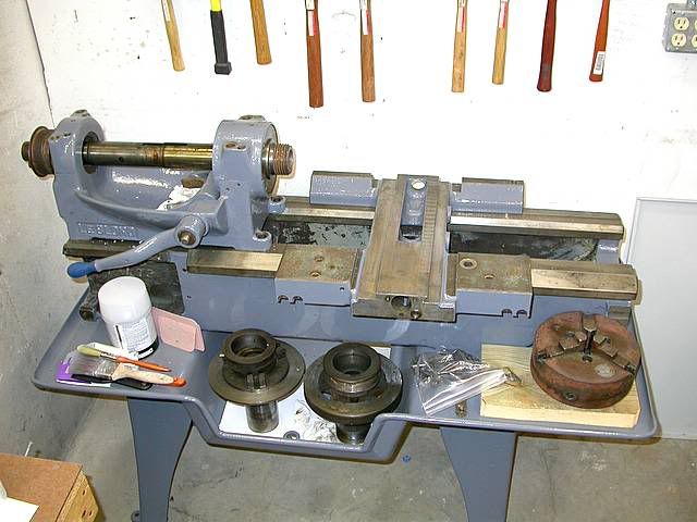
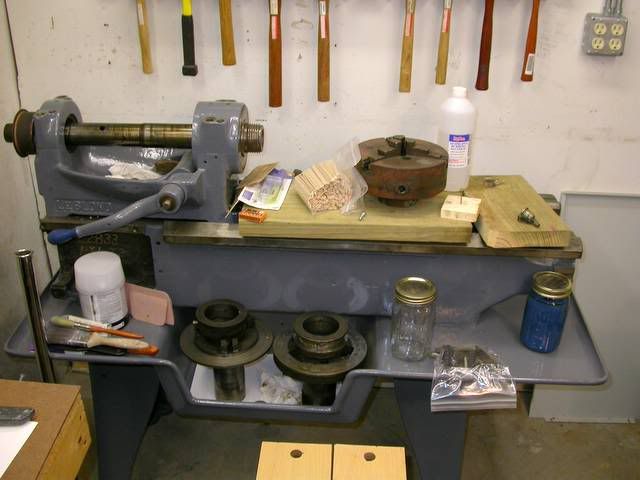
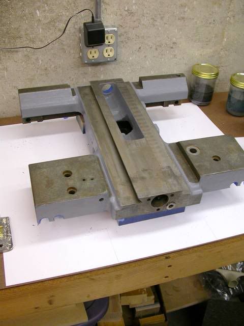
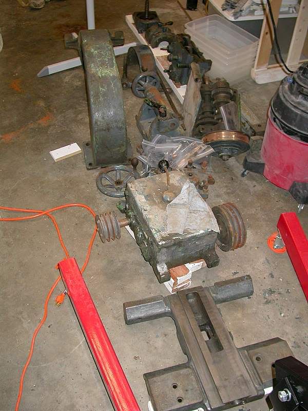
In addition to what was on the lathe, I had quite a few other parts for it:
Image hosted by Photobucket.com
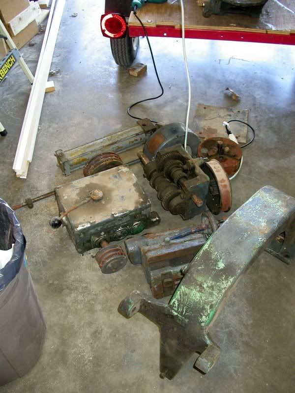
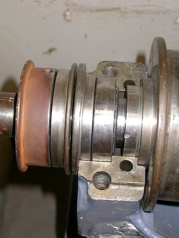
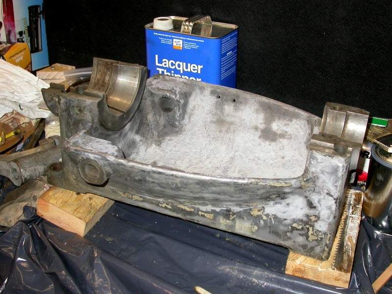
On the top row on the left is a hydraulic cylinder. At some point, the lathe was probably setup with some type of hydraulic automation. I think it bolted to the side of the carriage. May have been used for drilling holes to a set depth. I don't think I'll be putting it back on, I really don't have a use for that function now, and I also don't have all the other parts for that. To the right of the cylinder is a cover that fits on the headstock, and to the right of that is the only chuck I have for it at the moment, a 3-jaw scroll chuck. Right below the chuck is a pulley. The visible part is for a flat belt that connects to the end of the spindle in the headstock. Attached to it (not visible) is a smaller v-belt pulley. Actually, they're both really sheaves, a pulley is a combination of a sheave and a belt. To the left of the sheave is the gearbox that controls the speed of the carriage and crosslide power feeds. This mounts on the front of the lathe bed, under the headstock. The sheave mentioned earlier mounts on the left side of this. Originally, when the lathe was driven from a line shaft, a flat belt would have powered the spindle directly. On the left end of the spindle is a small flat sheave, which is connected via flat belt to the larger sheave shown here. However, when the lathe was converted to use an electric motor, they used the system in reverse. Power is transmitted to the v-belt sheave attached to the flat belt sheave, which then sends power up to the spindle. This is where the gearbox on the far left side of the photo comes in. It was mounted on the support shown in the lower right part of the photo, which mounted on the rear on the left side of the lathe. The motor was connected to the gearbox, which can select among 9 speeds, which is then connected to the v-belt sheave mentioned earlier. Finally, hiding under the gearbox bracket is the tailstock. There is also a chip tray, not shown, that mounts between the bed and the legs. This catches are the metal shavings (swarf), and also catches any coolant, if I'm using it.